Overheating in a high-density SIM bank is rarely a device defect. It is almost always a mismatch between what the installation was sized for and what it actually does when every slot is populated and traffic is running.
This article covers the path from power to heat to intermittent faults, why sizing has to come from peak draw rather than idle, the difference between room temperature and rack intake temperature, airflow and spacing at density, and the checks that verify behaviour after the installation has reached steady state rather than during commissioning.
Why does a high-density SIM bank overheat?
Every watt of consumption becomes heat inside it.
Populating every slot raises consumption, and consumption appears as heat that has to leave through the same surfaces the equipment is mounted against.
The scaling is not intuitive. A partially populated unit has empty volume that helps move air and reduces the total heat load; a fully populated one has neither, so the same enclosure cools fewer watts per slot than it did when half the positions were occupied. Density therefore changes the thermal problem rather than merely increasing it, which is why a unit that ran cool at twenty per cent occupancy can be marginal at full population.
The second factor is traffic. Modules draw more when transmitting than when idle, so the thermal load follows the message profile rather than the clock. A rack that runs cool overnight and warm during a campaign has a thermal design that depends on how it is used, and any plan that assumes average load will be wrong during the hours that matter.
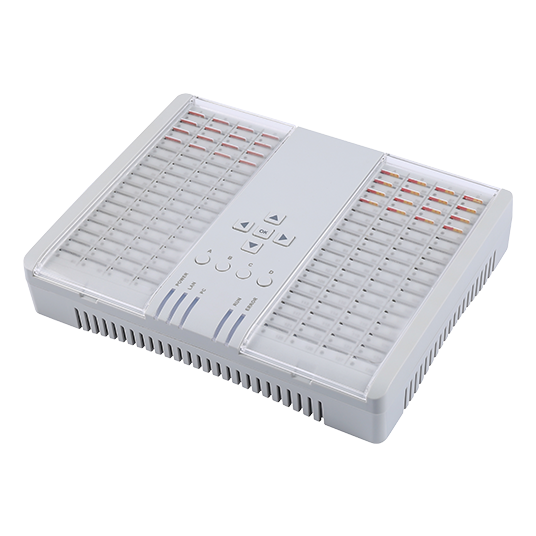
Should a high-density SIM bank rack be sized from idle or peak draw?
From peak, with the peak defined.
Sizing from idle produces an installation that works perfectly until the first busy hour and then behaves unpredictably, because the margin was never present.
Peak is harder to define than it sounds, because the relevant peak is not the sum of every nameplate figure. It is the draw that occurs when the largest realistic number of slots transmit at the same time, which depends on the platform’s scheduling and on the message profile. That figure has to be measured rather than calculated, and the measurement belongs in the commissioning record.
Two measurements make the peak concrete. The first is instantaneous current at the rack feed during a full campaign. The second is the same current over a sustained period, because thermal problems are a function of duration as much as of magnitude. A momentary peak that lasts a second and a sustained load at eighty per cent of it have very different consequences for a closed enclosure.
A third figure is worth capturing because it explains many disagreements about whether a rack is overloaded: the ratio between the sustained figure and the idle figure. A rack that draws three times its idle current under load is a rack whose thermal behaviour is dominated by traffic rather than by standby consumption, and any cooling plan based on the idle number will be wrong for the hours that matter. Recording the ratio makes the dependency explicit and gives the facilities conversation a single number to work with instead of a description of symptoms.
| Measurement | What it tells you | When to take it |
|---|---|---|
| Idle current | The floor, not the sizing figure | At commissioning |
| Peak current | The design load for supply and cooling | During a full campaign |
| Sustained current | Whether heat will accumulate | Over at least one busy hour |
| Rack intake temperature | The air the equipment actually receives | At the same time as the current readings |
Is rack intake temperature the same as room temperature?
No, and the difference is the whole point.
Air entering the equipment has already passed through other equipment or through a confined space, so intake temperature is typically higher than the room figure the facilities team reports.
The gap comes from recirculation. Air heated by one unit rises, and if the rack has no separation between its intake and exhaust sides, a proportion of that warm air returns to the intake of the unit above. The room sensor reads a comfortable value while the equipment breathes something considerably warmer, and the difference is invisible in any facility dashboard.
Measure intake at the equipment, not the room, and measure it during load. Where the equipment is specified to a harmonised terminal standard such as ETSI EN 301 511, the environmental conditions assumed by the specification are the reference; the installation either meets them or it does not, and the only way to know is to measure in place.
Airflow and spacing at density
Space between units is a component, not a luxury. Blind panels and gaps allow air to move where it is needed and reduce the recirculation that raises intake temperature. Installing units directly against each other removes that path, and the effect compounds with each additional unit in the rack.
Direction matters as much as volume. Equipment designed to draw air from the front and exhaust to the rear behaves predictably when those two sides are kept separate, and unpredictably when warm exhaust air is allowed to return. Where the rack cannot be arranged with a clear front-to-rear path, the honest conclusion is that the installation cannot support full density, and reducing the population is a legitimate remedy rather than a failure.
Resistibility recommendations for telecom equipment, including ITU-T K.20, ITU-T K.21 and the test regime described in ITU-T K.44, define the environments equipment may be expected to tolerate. They are not cooling guides, but they are a useful reference for the classes of installation and for the vocabulary of environmental testing.
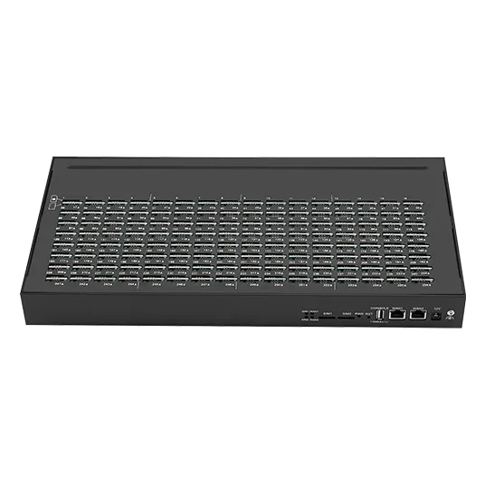
How do thermal faults present?
Intermittently, and in a pattern that repeats.
Thermal faults appear after a period of load rather than at the start, they cluster on the positions with the least airflow, and they disappear when traffic stops.
That signature is what separates a thermal problem from a power problem, which appears at the instant load rises, and from a radio problem, which is stable per position regardless of load. Because thermal faults arrive late, they are often misattributed to whichever campaign happened to be running when someone noticed, and the evidence needed to correct that impression is simply elapsed time per event.
Record, for each fault, the slot, the rack row, the elapsed transmission time and the intake temperature. A day of data usually shows the pattern, and the pattern names the cause. Where the recording is absent, the default conclusion is that the equipment is unreliable, which leads to replacement rather than to a fix.
One caution about remediation: lowering the temperature of a room does not necessarily lower the intake temperature at the equipment, because the difference between the two is produced by recirculation rather than by the room itself. Measure at the equipment before and after any change to the room, and keep the pair. Changes to cooling that are made without a before-and-after measurement are indistinguishable from changes that had no effect, and the next person to review the installation will have no basis for keeping them.
Verifying behaviour after steady state
Commissioning happens cold, and the interesting state is hot. Verify after the installation has run at load for long enough for temperatures to stabilise, which in a populated rack is usually measured in tens of minutes rather than in seconds. Readings taken in the first two minutes describe the enclosure at room temperature and predict nothing.
Two checks belong in the post-steady-state record: stability of the intake temperature over the load period, and the absence of any fault correlation with elapsed time. Where intake temperature continues to climb rather than levelling, the installation has no equilibrium at that density, and the remedy is airflow or population rather than more monitoring.
Physical and environmental protection is a recognised control family, and the way it is organised in NIST SP 800-53 Rev. 5 is a reasonable structure for documenting what the installation is designed to tolerate, even outside a regulated environment. The value of writing it down is that the assumptions become explicit rather than implicit in whatever was installed first.
A thermal plan for a new deployment
A thermal plan is short and it prevents most of the failures described above. It records the intended population, the measured peak current, the intake temperature at load, the airflow arrangement, and the load profile the figures were taken under.
- Measure idle, peak and sustained current before finalising the rack layout.
- Decide the maximum population the airflow arrangement can support, and write it down.
- Measure intake temperature at the equipment during a busy hour.
- Keep intake and exhaust paths separate, using blanking where gaps exist.
- Record the load profile the readings were taken under.
- Re-measure after any change to population, layout or campaign size.
The final step is the one that keeps the plan true. Populations grow one unit at a time, and each addition changes the thermal picture without changing the documentation; re-measuring after each change is what keeps the documented limit and the real one aligned.
Measure at load, not at commissioning. Send your rack population, peak current and intake temperature to service@telarvo.com, or review the published configurations on the SIM pool range and the SMS modem range. Telarvo publishes the SIMBANK and SIMPOOL ranges on its product pages, and the configurations referenced above come from those listings.
FAQ
Is overheating covered by the hardware warranty?
Installation conditions are usually outside the scope of a hardware warranty, so a thermal failure caused by airflow or population is normally treated as an installation issue rather than a defect. That is one reason to record intake temperature and population: the record distinguishes a device fault from an environment that exceeded the design conditions. It also tells you what to change, because a device swap in the same position will fail the same way.
Does adding a fan solve a thermal problem?
It can, if the underlying problem is air movement rather than air temperature. Adding airflow to an installation that is drawing already-warm air moves the warm air faster without lowering its temperature. Measure intake temperature first; if it is high, the fix is upstream of the rack. Recirculation inside a closed cabinet is the case where more airflow genuinely helps.
Why does the fault only appear during large campaigns?
Because thermal load follows transmission. A campaign raises both the current draw and the heat produced, and a fault that needs twenty minutes of sustained operation to appear will not show up during idle periods or during short tests. Elapsed time per event is the measurement that reveals it. One number per bank, from idle to the first fault, is enough to size the maintenance decision.
What should the thermal record contain?
Intended population, measured idle and peak current, sustained current over a busy hour, intake temperature at the equipment, the airflow arrangement, and the load profile the readings were taken under. Re-measure after any change to population or layout, and keep the record with the configuration rather than in a project folder. The intake figure is the one to compare against the class the equipment expects.