Module life is not a property of the module alone. It is the result of how the module is powered, how it is cooled, and how hard it is worked, and all three are things a buyer can inspect before purchase.
This article sets out the design factors that determine how long modules last in continuous operation, what fails first when those factors are wrong, and how to verify a longevity claim rather than accept it.
What determines industrial modem module longevity in continuous operation
Temperature, power quality and duty cycle, in that order.
A cellular module in a modem pool runs continuously for years, which is a different condition from the intermittent use the same module sees in a consumer product. Under continuous operation the dominant wear mechanisms are thermal and electrical: the module and its surrounding components expand and contract with each temperature cycle, and the power supply is asked to deliver a stable voltage through every transition the radio makes. Design that anticipates this produces a device that lasts; design that does not produces one that works perfectly for a year and then does not.
The distinction between industrial and consumer equipment is therefore a design intent rather than a component list. The same module can appear in both. What differs is the margin around it: how much headroom the power stage has, how much surface is available to dissipate heat, whether the enclosure moves air at all, and how much of the module’s duty cycle is spent in its highest-power state.
| Design factor | What good looks like | How to check it |
|---|---|---|
| Thermal margin | Temperature at the module stays well below its limit under load | Measure at the module, under peak load, in the installed position |
| Airflow | Designed movement rather than relying on convection alone | Inspect the enclosure and measure intake and exhaust |
| Power stage | Headroom above the transient the radio draws | Ask for the rating and measure the transient |
| Duty cycle | Configurable pacing so the radio is not sending continuously | Read the documentation and test the setting |
Thermal design as the primary factor
Heat is the largest single contributor to shortened module life.
Every radio transmission dissipates energy as heat, and a pool of modules transmitting continuously concentrates that heat in a small volume. Where it cannot leave, the module operates at a higher temperature than its design assumes, and the consequences arrive gradually: the failure rate rises first at the top of a rack, the modules that fail are the ones that ran hottest, and the pattern looks random until the temperature is measured.
What can be verified is limited but useful. The environmental conditions equipment is expected to withstand in a fixed installation are classified in ETSI EN 300 019-1-3, one of the ETSI standards, and a device declared against a class is claiming that it functions within that class. The measurement that proves the claim at a site is the module temperature under sustained load, taken inside the enclosure rather than in the room, and recorded so that it can be compared after any change to the rack.
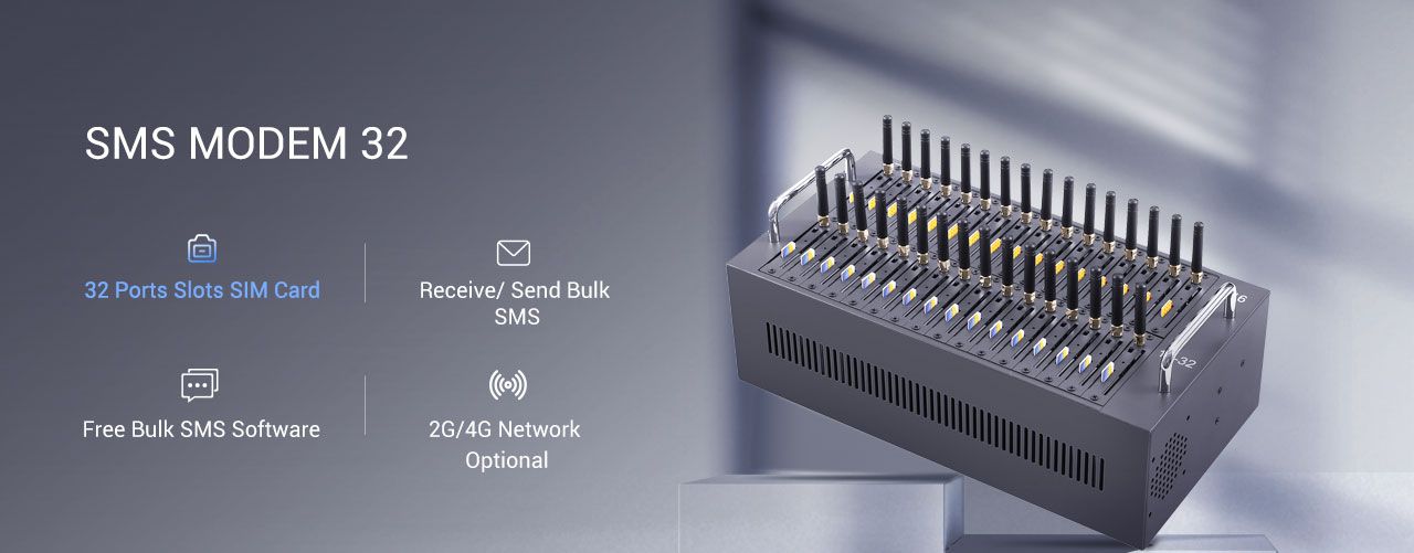
The design details that indicate a serious thermal solution are visible without instruments. A metal chassis rather than a plastic one, vents that correspond to a path the air can actually follow, spacing between modules rather than a solid block, and a specification that states an operating range instead of omitting it. Where a product page publishes no thermal information, the question to ask is what the measured module temperature is at full duty cycle in a specified ambient, and the honest answer from a supplier will be a measurement rather than a claim.
Power quality and voltage stability
A radio module draws current in bursts, and the supply has to absorb them.
Transmission is not a steady load. The module draws a comparatively small current while idle and a much larger one while transmitting, and it does so repeatedly. A power stage with insufficient headroom droops during those bursts, and the module responds in ways that look like software faults: a reset that appears in the log as an unexplained restart, a dropped registration, a command that returns an error with no apparent cause. Those symptoms are frequently attributed to firmware and are frequently electrical.
What can be verified is the rating against the requirement and the behaviour under load. Resistibility expectations for telecommunications equipment, including what a device should tolerate on its power and signal ports, are described in ITU-T K.20, with test methods in ITU-T K.21 and ITU-T K.44. Asking which of those the equipment is declared against produces a concrete answer where a general claim about power quality produces none.
Earthing and bonding belong in the same conversation. A rack assembled without attention to bonding can produce circulating currents and intermittent faults that are extremely difficult to diagnose after installation and trivial to prevent before it.
Duty cycle and pacing
How hard the radio is worked is a design decision, not a fixed property.
A module that transmits continuously spends its life at its highest power state and at its highest temperature. The same module paced to send at a rate the workload actually requires drops back to idle between sends, which lowers both the average temperature and the thermal cycling that the components experience. Over years of operation, that difference is the single most controllable factor in how long a pool lasts, because everything else was decided by the manufacturer.
Pacing is therefore a longevity control as well as a throughput control, and its value depends on whether it is configurable and persistent. A device that offers a fixed interval and no way to set it per subscription leaves the operator with one lever: reduce the workload. A device with a configurable and exportable rate policy lets the operator trade throughput against equipment life deliberately, and record the decision.
The radio behaviour that pacing moderates is described in the transmission characteristics of the technology, for example in 3GPP TS 45.005 for the GSM radio interface, which sets the power classes the module operates within. Knowing the class matters because a module at the edge of coverage transmits at higher power to be heard, which means that installing a pool in a poorly served location raises its operating temperature and shortens its life in a way that no in-rack change will fix.
What fails first and why
The failures are usually at the edges of the thermal and electrical margins.
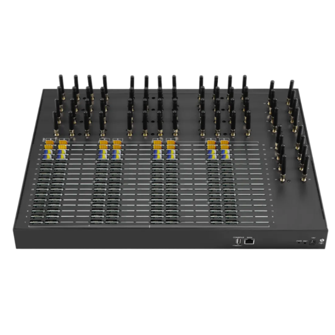
Four items account for most of the failures seen in continuously operated modem pools. The power supply, which fails first because it carries the burst current and has the least thermal mass. The module itself, where it has been running hot for long enough. The connectors, particularly where the SIM path is mechanical and the environment cycles in temperature. And the fan or airflow path, where one is used and where dust accumulation quietly removes the margin the design assumed.
The pattern of failure is more informative than any single failure. Where failures cluster in the highest position of a rack, the cause is thermal and the response should be airflow rather than replacement. Where failures follow a particular model in a mixed pool, the cause is likely that model. Where failures follow a particular rack or site, the cause is environmental, and the site is the thing to change. Recording the position, the model and the date for every failure is what makes the pattern visible at all.
Dust belongs on the list because it is the failure mode that maintenance prevents. A filter that is never cleaned stops doing its job and starts restricting airflow, and a rack that has run for two years without inspection has accumulated whatever the room contains. A scheduled inspection and cleaning, recorded, is the cheapest reliability measure available in most installations.
Verifying claims about longevity
Ask for measurements, the conditions they were taken under, and the basis of comparison.
A claim about longevity is only meaningful with three pieces of context: what was measured, under what conditions, and over what period. A temperature figure taken at idle in a conditioned lab says little about a pool under full load in an equipment room. A statement that components are industrial grade says nothing about the margin around them. A comparison against an unnamed competitor is not a comparison.
The questions that produce usable answers are concrete. What is the measured module temperature under sustained full duty cycle, and at what ambient? What is the power stage rated for against the module’s transmit transient? Which environmental class is the equipment declared against? What is the maintenance interval the design assumes, and what does it consist of? What failure data exists from field returns, and what were the conditions?
Where a supplier cannot answer some of those, the honest response is to note the gap rather than to fill it with an assumption. A supplier that answers three of five precisely is a better bet than one that answers all five vaguely, because precise answers can be checked and vague ones cannot.
A durability checklist
The checklist covers the factors that decide module life and the measurements that show where a deployment stands. It is written to be completed at commissioning and repeated, because the useful comparison is against the same position and the same load rather than against a specification.
- Measured module temperature under sustained load, in the installed position.
- Intake and exhaust temperatures at the lowest and highest units in the rack.
- Environmental class the equipment is declared against, and the class of the room.
- Power stage rating against the module transmit transient, confirmed in writing.
- Configurable, persistent and exportable pacing policy.
- Bonding and earthing arrangement recorded in the as-built documentation.
- Maintenance interval, including filter and airflow inspection.
- Failure log recording position, model and date for every unit replaced.
Ask for the measurement, not the adjective. Send your ambient conditions, duty cycle and maintenance interval to service@telarvo.com, or review the published configurations on the SMS modem range and the SMS modem solution page. Telarvo publishes the SK-SMS gateway range, the TYH modem pools and the TGW SMS machine on its product pages, and the configurations referenced above come from those listings.
FAQ
What makes an industrial modem module last longer?
Thermal margin, power quality and duty cycle, in that order. The same module can appear in consumer and industrial equipment, and what differs is the margin around it: headroom in the power stage, surface area and airflow to dissipate heat, and how much of the time the radio spends in its highest-power state. All three are inspectable before purchase. Record the ambient temperature with the reading, because the reading alone cannot be compared.
What typically fails first in a continuously operated modem pool?
The power supply, because it carries the transmit burst current and has the least thermal mass. The module follows where it has run hot for long enough, then the mechanical connectors, and then the airflow path where dust has quietly removed the designed margin. The pattern across positions and models is more informative than any single failure. Repeat the measurement after any change to the rack, since the number belongs to the position.
How can I verify a supplier claim about module longevity?
By asking for the measurement, the conditions, and the period. A temperature figure taken at idle in a lab says little about a pool under full load in an equipment room. Ask for module temperature at sustained duty cycle and a stated ambient, the power stage rating against the transmit transient, the environmental class the equipment is declared against, and any field return data with its conditions.
Does pacing affect how long modules last?
Yes, it is the most controllable factor after the equipment is installed. A module transmitting continuously operates at its highest power state and temperature, while the same module paced to the rate the workload needs returns to idle between sends, which lowers its average temperature and reduces thermal cycling. That makes a configurable and persistent pacing policy a longevity control as well as a throughput control.
{
“@context”: “https://schema.org”,
“@type”: “FAQPage”,
“mainEntity”: [
{
“@type”: “Question”,
“name”: “What makes an industrial modem module last longer?”,
“acceptedAnswer”: {
“@type”: “Answer”,
“text”: “Thermal margin, power quality and duty cycle, in that order. The same module can appear in consumer and industrial equipment, and what differs is the margin around it: headroom in the power stage, surface area and airflow to dissipate heat, and how much of the time the radio spends in its highest-power state. All three are inspectable before purchase. Record the ambient temperature with the reading, because the reading alone cannot be compared.”
}
},
{
“@type”: “Question”,
“name”: “What typically fails first in a continuously operated modem pool?”,
“acceptedAnswer”: {
“@type”: “Answer”,
“text”: “The power supply, because it carries the transmit burst current and has the least thermal mass. The module follows where it has run hot for long enough, then the mechanical connectors, and then the airflow path where dust has quietly removed the designed margin. The pattern across positions and models is more informative than any single failure. Repeat the measurement after any change to the rack, since the number belongs to the position.”
}
},
{
“@type”: “Question”,
“name”: “How can I verify a supplier claim about module longevity?”,
“acceptedAnswer”: {
“@type”: “Answer”,
“text”: “By asking for the measurement, the conditions, and the period. A temperature figure taken at idle in a lab says little about a pool under full load in an equipment room. Ask for module temperature at sustained duty cycle and a stated ambient, the power stage rating against the transmit transient, the environmental class the equipment is declared against, and any field return data with its conditions.”
}
},
{
“@type”: “Question”,
“name”: “Does pacing affect how long modules last?”,
“acceptedAnswer”: {
“@type”: “Answer”,
“text”: “Yes, it is the most controllable factor after the equipment is installed. A module transmitting continuously operates at its highest power state and temperature, while the same module paced to the rate the workload needs returns to idle between sends, which lowers its average temperature and reduces thermal cycling. That makes a configurable and persistent pacing policy a longevity control as well as a throughput control.”
}
}
]
}