Continuous operation is an operational commitment rather than a product feature, and a 32-port modem that is suitable for it is one that can be maintained without being switched off. This article covers what that demands and how to plan for it.
It sets out the thermal, electrical and duty-cycle conditions that continuous operation imposes, how maintenance windows are planned when there is no quiet hour, and which measurements predict a failure early enough to act on.
What a durable 32-port SMS modem for 24/7 use demands
It demands that nothing in the deployment requires the device to stop.
A 32-port modem in a 24/7 deployment is expected to work every hour of every day, which rules out the maintenance approach used in deployments that have a quiet period. There is no window in which the device can be restarted without consequence, no hour in which the load is low enough that a partial outage goes unnoticed, and no opportunity to install a change and observe it without risk. Those constraints move the design work from the device specification to the surrounding arrangement.
Three consequences follow. The device must be maintainable while running, which in practice means replacing a module or a card rather than the chassis, and being able to change configuration without a restart. The capacity must tolerate the loss of a portion of the pool, because a device that provides exactly the required throughput has no reserve for a module being replaced. And the deployment must have a way to be updated on a subset first, so that a change is tested on the smallest unit of the estate rather than across all of it.
What continuous operation does not demand is a more exotic device. It demands a design in which the device is not the only thing between the workload and a service interruption, and it demands a maintenance practice that assumes no downtime is available.
| Requirement | What it implies |
|---|---|
| Maintainable while running | Module-level replacement, configuration changes without restart |
| Capacity with reserve | More ports than the peak requires, or a second unit |
| Incremental changes | Update a subset first, with a tested rollback |
| Remote diagnosis | Per-port state and logs readable without visiting |
Thermal design and its effect on life
In continuous operation the thermal margin is consumed slowly and then all at once.
A module that runs continuously at a higher temperature than its design assumes does not fail immediately. It fails earlier than it otherwise would, and the failures cluster in the position that ran hottest. In a 32-port chassis with modules arranged vertically, that position is usually at the top, where the air arriving has already passed other modules, and the difference between the top and the bottom is the measurement that describes the thermal design in practice.
Two checks establish where the deployment stands. The first is the temperature at the module under sustained load, measured inside the enclosure rather than in the room. The second is the environmental class the equipment is declared against, compared with the class the room provides; the classification for fixed installations is defined in ETSI EN 300 019-1-3, one of the ETSI standards. Where the room is warmer than the class assumes, the failure rate in that deployment differs from any figure derived for the reference conditions.
Airflow maintenance belongs to the same subject rather than to general housekeeping. Dust on a filter or across a heatsink reduces the margin gradually, and the effect is invisible until the ambient temperature rises in summer, at which point the pool fails in a way that looks seasonal and sudden. An inspection interval recorded in the maintenance plan, and a note of the condition found, is the control that prevents it.
Power quality and voltage stability
Continuous operation exposes a supply that a shorter duty cycle would tolerate.
A radio module draws current in bursts as it transmits, and the power stage has to absorb those transitions thousands of times a day. A stage with insufficient headroom produces symptoms that are attributed to software: an unexplained restart, a module that drops its registration and returns, a command that fails without an obvious cause. Those symptoms appear more often in a 24/7 deployment not because the fault is different but because there are more opportunities for it to occur.
The resistibility expectations for telecommunications equipment, covering what a device should tolerate on its power and signal ports, are described in ITU-T K.20, with the associated test methods in ITU-T K.21 and ITU-T K.44. Asking which of these the equipment is declared against produces a verifiable answer, and a device declared against a resistibility standard is one that has been tested against disturbances rather than merely designed to tolerate them.
Bonding and earthing are the part of the electrical arrangement that receives the least attention and causes the most intermittent faults. A rack assembled without consistent bonding can produce small circulating currents that affect modules unpredictably, and the fault is difficult to diagnose after installation and straightforward to prevent before it. Recording the arrangement in the as-built documentation is what makes it checkable later.
Duty cycle management through pacing
The rate the workload needs is usually lower than the rate the device can achieve.
Running a 32-port pool at its maximum sustained rate is a choice, and it is rarely the one that the workload requires. Pacing the sends to a rate derived from the actual requirement lowers the average temperature of every module, reduces the thermal cycling they experience, and leaves headroom for the moments when the workload genuinely peaks. Over years of continuous operation, that is the largest controllable factor in how long the pool lasts.
The pacing policy also has to be persistent and exportable to be useful in a 24/7 deployment. A policy that exists only in the running configuration is lost when the device is replaced, which in a continuous deployment happens at the worst possible moment. Exporting the configuration, recording the firmware version it belongs to, and storing both outside the device is what allows a replacement to be brought into service without a rebuild.
One caution applies to aggressive pacing. A rate set far below what the subscriptions and modules can sustain leaves capacity unused and may push the queue long enough to breach a response-time requirement. The sensible setting is derived from the required peak rather than from a general preference for lower rates, and it should be reviewed when the workload changes rather than set once at commissioning.
Maintenance windows and how to plan them
Where there is no quiet hour, maintenance has to be designed rather than scheduled.
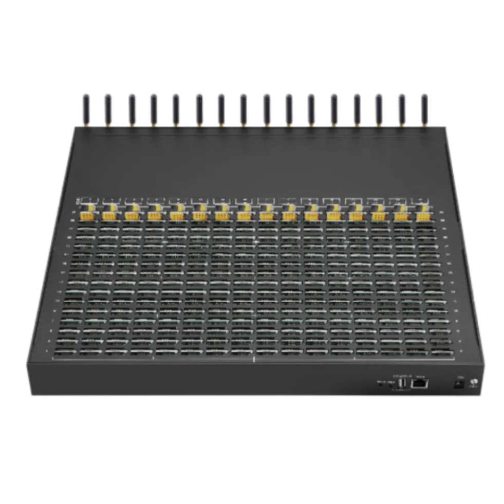
The alternative to a maintenance window is a maintenance method. Three approaches cover most continuous deployments. Module-level replacement, where a single module or card is swapped while the chassis continues to serve the remaining ports, which reduces the impact to a fraction of capacity rather than losing the device. Rolling updates across a pool, where one unit is taken out, updated and returned before the next is touched, which requires the pool to have enough spare capacity to absorb the loss. And configuration changes applied without a restart, where the device supports them, which removes the most common reason for a service interruption in the first place.
Whichever method is used, it needs two things to be safe. A rollback path that has been tested on a single unit rather than assumed, and a record of the change, because a fault appearing days later is only diagnosable if it can be read against what changed. Both belong in the maintenance plan alongside the interval rather than in the engineer’s memory.
Spares are the other half of the plan. A module held on site converts a replacement from a logistics exercise into a task, and the number to hold follows from the failure rate and the lead time rather than from a preference. Where the lead time exceeds the acceptable outage, the spare is not optional.
Indicators that predict a failure
Failures in continuous operation are usually preceded by a period of degraded behaviour.
Five measurements move before a module fails. The temperature at the module, if it rises against the same load and conditions, indicates a thermal path degrading. The time to complete a message, if it lengthens for one port while its neighbours hold steady, indicates a module or subscription problem. The registration history, if one card begins to re-register more often, indicates a developing issue. The current drawn by the unit, if it rises against the same workload, indicates an electrical problem. And the rate of failed sends on one port, if it diverges from the others, indicates that the port is on its way out.
None of those is conclusive on its own, and all of them are visible in data the device already produces. What makes them useful is a baseline recorded at commissioning, since a trend requires something to be a trend against. The operational practice of keeping and reviewing system records is described in NIST SP 800-123, which is aimed at server hardening but applies to any device expected to run unattended.
The practical discipline is to replace on a trend rather than on a failure. In a deployment with no maintenance window, a module showing a clear trend is a planned replacement during a rolling change; the same module left until it fails is an unplanned one at whatever hour it chooses.
A durability checklist
The checklist covers the conditions and measurements that make continuous operation supportable. Each item produces a recorded figure or a documented arrangement, and the set is intended to be completed at commissioning and revisited when the site or the load changes.
- Module temperature under sustained load, measured inside the enclosure.
- Environmental class of the room against the class the equipment expects.
- Airflow inspection interval recorded, with filter condition noted.
- Resistibility standard the equipment is declared against, confirmed in writing.
- Bonding and earthing arrangement recorded in the as-built documentation.
- Pacing policy derived from the required peak, exported and stored outside the device.
- Module-level replacement possible without stopping the chassis.
- Spare modules held against the lead time and the acceptable outage.
- Baseline recorded at commissioning: temperature, handling time, registration, current, failure rate.
Design for maintenance without downtime, then choose the ports. Send your required peak, maintenance constraints and spares plan to service@telarvo.com, or review the published configurations on the SMS modem range and the SMS modem solution page. Telarvo publishes the SK-SMS gateway range, the TYH modem pools and the TGW SMS machine on its product pages, and the configurations referenced above come from those listings.
FAQ
What makes a 32-port SMS modem suitable for 24/7 operation?
Three things beyond the specification. The ability to be maintained while running, which usually means module-level replacement and configuration changes without a restart. Enough spare capacity that a module under replacement does not reduce throughput below the requirement. And remote diagnosis, so that a developing problem is visible in per-port state and logs without a site visit. Confirm the maintenance method before the purchase, because it determines what the design has to allow.
How do I maintain a modem pool with no quiet hour?
By replacing the maintenance window with a maintenance method. Replace single modules while the chassis continues serving the remaining ports, roll updates across a pool one unit at a time with spare capacity to absorb the loss, and apply configuration changes without a restart where the device supports it. Each method needs a tested rollback and a record of what changed.
Which measurements predict a modem module failure?
Five: a rising module temperature at the same load, lengthening handling time on one port while neighbours hold steady, increasing re-registration on one card, rising current draw at the same workload, and a failure rate diverging on a single port. All appear in data the device already produces, and all require a baseline recorded at commissioning to be readable as a trend.
Does pacing extend the life of modules in continuous operation?
Yes, and it is the largest controllable factor after installation. Sending at the rate the workload requires, rather than at the maximum the device can achieve, lowers the average module temperature and reduces thermal cycling, while leaving headroom for genuine peaks. The setting should be derived from the required peak and reviewed when the workload changes, not fixed once at commissioning.
{
“@context”: “https://schema.org”,
“@type”: “FAQPage”,
“mainEntity”: [
{
“@type”: “Question”,
“name”: “What makes a 32-port SMS modem suitable for 24/7 operation?”,
“acceptedAnswer”: {
“@type”: “Answer”,
“text”: “Three things beyond the specification. The ability to be maintained while running, which usually means module-level replacement and configuration changes without a restart. Enough spare capacity that a module under replacement does not reduce throughput below the requirement. And remote diagnosis, so that a developing problem is visible in per-port state and logs without a site visit. Confirm the maintenance method before the purchase, because it determines what the design has to allow.”
}
},
{
“@type”: “Question”,
“name”: “How do I maintain a modem pool with no quiet hour?”,
“acceptedAnswer”: {
“@type”: “Answer”,
“text”: “By replacing the maintenance window with a maintenance method. Replace single modules while the chassis continues serving the remaining ports, roll updates across a pool one unit at a time with spare capacity to absorb the loss, and apply configuration changes without a restart where the device supports it. Each method needs a tested rollback and a record of what changed.”
}
},
{
“@type”: “Question”,
“name”: “Which measurements predict a modem module failure?”,
“acceptedAnswer”: {
“@type”: “Answer”,
“text”: “Five: a rising module temperature at the same load, lengthening handling time on one port while neighbours hold steady, increasing re-registration on one card, rising current draw at the same workload, and a failure rate diverging on a single port. All appear in data the device already produces, and all require a baseline recorded at commissioning to be readable as a trend.”
}
},
{
“@type”: “Question”,
“name”: “Does pacing extend the life of modules in continuous operation?”,
“acceptedAnswer”: {
“@type”: “Answer”,
“text”: “Yes, and it is the largest controllable factor after installation. Sending at the rate the workload requires, rather than at the maximum the device can achieve, lowers the average module temperature and reduces thermal cycling, while leaving headroom for genuine peaks. The setting should be derived from the required peak and reviewed when the workload changes, not fixed once at commissioning.”
}
}
]
}