An integrator chooses hardware for the years after the handover, not for the week of the installation. Rack mounting, documentation and spares are the parts of that decision that clients notice last and support teams notice first.
This article sets out what an integrator is actually signing up to support, how the rack form factor affects site acceptance, why power, thermal and antenna planning determine whether a project stays profitable, and how documentation and spares separate one vendor from another.
What an integrator has to support after handover of a rack-mount GSM gateway
The project ends when the invoice is paid; the obligation does not.
By the time a client signs off a deployment, the integrator has taken on a support commitment that runs for years. That commitment is what the hardware choice is really being made against. The questions that matter are how quickly a fault can be diagnosed remotely, whether a failed unit can be replaced without re-engineering the rack, whether the client’s own team can read the alarms, and whether the vendor will still recognise the model in three years when a spare is needed.
Equipment that is awkward to mount, awkward to document or awkward to replace converts directly into unbillable time. That is the commercial reason rack hardware wins in integration projects, and it is more decisive than any technical specification, because the cost of support is proportional to the number of surprises the installation produces after commissioning.
| Support task | What makes it cheap | What makes it expensive |
|---|---|---|
| Remote diagnosis | Per-port state and readable logs | Aggregate status with no per-port detail |
| Unit replacement | Standard rack width and front-access cabling | Non-standard mounting or rear-only access |
| Client handover | Versioned documentation and alarm list | Undocumented alarms and untracked firmware |
| Capacity change | Modular expansion in the same chassis | Replacing the whole unit for a few more ports |
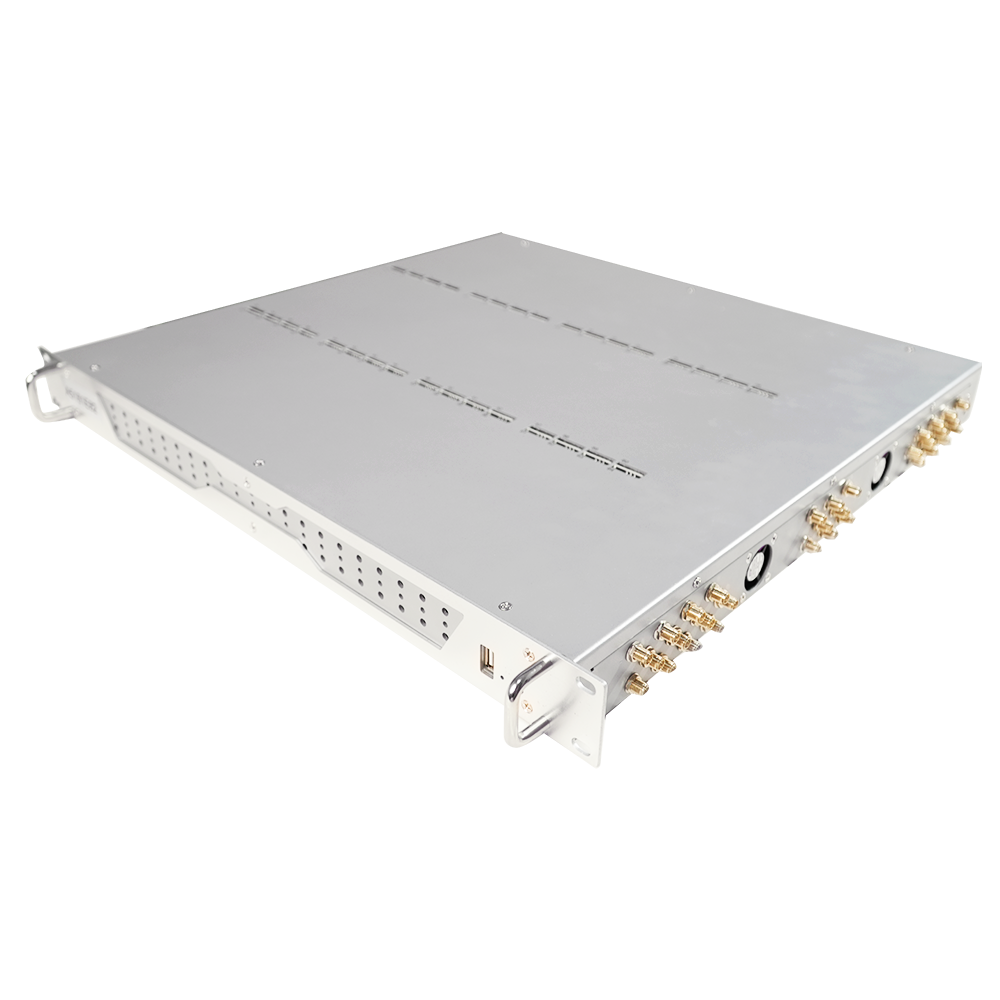
Rack form factor and site acceptance
Rack width is a constraint imposed by the room, not a preference.
A data centre or equipment room is designed around a standard width and a fixed mounting pattern, and equipment that does not conform has to be accommodated rather than installed. In practice this shows up in three ways: a unit that needs a shelf instead of rails, cabling that has to be dressed around an awkward connector layout, and airflow that conflicts with the direction the room is designed to move air. Each of them is a variation to be agreed with the client and a note to be carried in the as-built documentation.
The antenna path is the part of the rack decision that is most often decided late and most often regretted. A rack-mounted gateway still needs radio frequency access that reaches outside the enclosure, which means the cable route, the connector type and the lightning protection are all part of the site design rather than an afterthought. The environmental conditions equipment should be able to withstand in a fixed installation are classified in ETSI EN 300 019-1-3, one of the ETSI standards, and matching the room to the class the equipment expects is a concrete acceptance criterion rather than a formality.
Frequency planning belongs alongside it. Where several operators are served from one rack, antenna separation and orientation determine whether the site behaves as designed, and the radio transmission characteristics of the technology are described in 3GPP TS 45.005. An integrator who documents the intended placement and the measured result at commissioning has an artefact that shortens every future visit.
Power, thermal and antenna planning
The three constraints interact, and solving them one at a time produces a rack that fails.
Power planning is about the immediate circuit and the earthing arrangement. Rack equipment is normally fed from a distribution unit, and the protection that equipment should provide against overvoltage and overcurrent is covered by the resistibility recommendations in ITU-T K.20 and the associated test methods in ITU-T K.21 and ITU-T K.44. Those documents also set expectations for bonding and earthing, which is the item most often omitted when a rack is assembled by people who are not telecoms specialists.
Thermal planning is about where the heat goes. High-density modem pools produce continuous heat from a small volume, and a rack that was designed for one chassis may not move enough air for three. The measurement that matters is the temperature at the intake of the lowest and highest units in the rack, not the room temperature displayed on a wall panel, because a temperature difference across a rack is exactly what causes the top unit to fail first.
Antenna planning is about the path from the module to the outside. Cable loss rises with length and connector count, so a run that looks short on a drawing can still deliver a marginal signal at the module. Recording the measured signal level at commissioning, for each unit and for each operator, gives the next engineer a baseline and gives the client evidence that the installation performs as specified.
Documentation quality as a differentiator
The manual is a support cost that is paid either now or later.
Documentation quality separates vendors more reliably than pricing at comparable specifications. A complete package includes the pinout or port mapping, the default configuration and the steps to change it, the alarm list with the meaning of each condition, the firmware update procedure with its rollback path, and the export and import format for configuration. Where any of those is missing, the integrator writes it, and the time spent writing it is time the project did not budget for.
The alarm list is the item worth checking first during evaluation. If a device can raise a condition that the documentation does not explain, the client will eventually call about it, and the call will be answered by guessing. A short list of well-documented alarms is more valuable operationally than a long list of undocumented ones.
Firmware version tracking is the second. A deployment with ten identical units running four different firmware versions is a deployment where a fix verified on one unit may not behave the same way on another. Recording the version in the as-built documentation, and treating an update as a change with its own record, is the practice that keeps a multi-client estate supportable; the general hardening context for the host systems around it is covered in NIST SP 800-123.
Spares and replacement strategy
A spare is only a spare if it can be configured.
The replacement strategy for rack hardware has two components: the physical unit and the configuration that makes it useful. A spare chassis in the integrator’s stores restores capacity as soon as it is installed, provided the configuration can be restored to it, which means an export exists outside the device and its firmware version is recorded. Without that, a replacement is a rebuild, and a rebuild during an outage takes longer than the outage the spare was bought to prevent.
The second component is commercial continuity. Equipment that is still supported three years after installation, with the same model numbers and a spares path, is worth more to an integrator than a marginally cheaper unit that is discontinued within a year. Asking about the model roadmap and the spare parts availability before a project is awarded is a standard question in integration work and one worth asking in writing.
The third is the maintenance window. Where the client cannot accept a gap, the spare is the answer; where the client can, a support arrangement with a defined response time is usually the cheaper choice. The decision follows from the service level, not from the hardware.
Multi-client separation
Integrators often serve several clients from one physical estate.
Where a rack holds equipment belonging to more than one client, or where one client’s traffic must not be visible to another, separation has to be designed rather than assumed. Three levels are available: separate physical units for each client, which is the clearest but the most expensive; separate chassis within a shared rack with independent management access; and shared hardware with logical separation, which is the cheapest and demands the most care in configuration and logging.
The management plane is where separation usually fails. A shared management network with common credentials means every client’s equipment is reachable from one console, which is convenient until it needs to be explained. Per-client credentials, per-client management access and per-client log retention remove that problem at the cost of some setup work, and where a client’s own staff need to read alarms, the access model should be agreed before the deployment rather than after the first support request.
A selection outline
The outline follows a rack deployment from the constraints of the room to the support arrangements after handover. The items are ordered by the point at which they are decided in a project rather than by importance, because a constraint that appears late is the one that changes the design.
- Rack width, mounting pattern and cabling access at the intended position.
- Environmental class of the room against the class the equipment expects.
- Power distribution, bonding and earthing arrangements for the rack.
- Airflow direction and the temperature at the top and bottom of the rack.
- Antenna route, connector count and the measured signal per unit at commissioning.
- Documentation package: port mapping, alarm list, update and rollback, export format.
- Spare unit, configuration export and firmware version recorded in the as-built.
- Separation model and management access for each client served from the rack.
Buy for the support years, not the installation week. Send your rack constraints, environmental class and client separation model to service@telarvo.com, or review the published configurations on the SMS gateway range and the SMS modem range. Telarvo publishes the SK-SMS gateway range, the TYH modem pools and the TGW SMS machine on its product pages, and the configurations referenced above come from those listings.
FAQ
Why do integrators prefer rack-mount gateways over desktop units?
Because the support obligation outlives the installation. A rack-mount unit fits the room as designed, can be replaced without re-engineering the position, and is usually delivered with the documentation an integrator needs for remote diagnosis. Desktop units can be perfectly reliable and still cost more over a project lifetime, because every deviation from the room standard becomes unbillable time. Record the answer at the start of the rack design rather than at the end of it.
What documentation should a rack-mount gateway include?
Five items. A port or pinout map, the default configuration with the steps to change it, an alarm list explaining every condition the device can raise, the firmware update procedure with a rollback path, and the export and import format for configuration. Missing any of them means the integrator writes it, and undocumented alarms are the item that generates the most avoidable support calls.
How should a rack with several GSM gateways be cooled?
By measuring the intake temperature at the lowest and highest units rather than trusting the room display. High-density modem pools produce continuous heat from a small volume, and the temperature difference across a rack is what causes the top unit to fail first. If the top and bottom intakes differ by much, airflow or rack layout needs attention before capacity is added.
How many gateways can share one antenna system?
There is no single number, because it depends on the bands in use, the separation between antennas and the signal conditions at the site. The safe approach is to plan the placement, then measure the signal at each unit during commissioning and record the result. Two units that interfere can often be resolved by physical separation and orientation rather than by adding equipment.