Pools scale in a way that is not linear in practice. An eight-port pool on a desk behaves as expected; the same design at 32 ports develops symptoms that look like network problems and are actually electrical, because 32 modules transmitting at once draw current in a pattern that a bus-powered chassis was not designed for.
This guide covers the physical limits that appear at this tier: the power a 32-port pool draws under load, how USB topology constrains throughput independently of the radios, how to diagnose a port that drops during a batch, and where the crossover to a 64-port or rack-mounted solution becomes worthwhile.
Why does a 32-port pool fail where an 8-port pool works?
Because the constraints change with the count.
The pool is not merely four times larger; it crosses two thresholds that a smaller pool does not reach.
The first threshold is power. Each module draws substantially more current while transmitting than while idle, and at 32 ports the simultaneous draw during a batch exceeds what a single bus-powered arrangement can supply. The second is topology. A host provides a finite number of USB controllers and ports, so a 32-port pool necessarily involves hubs, and hub arrangement determines whether the modules share bandwidth in a way that limits aggregate throughput.
Neither threshold announces itself. Power appears as modules that deregister during a batch and recover afterwards, which reads as a network fault. Topology appears as throughput that stops rising when more modules are added, which reads as a network limit rather than as a host-side one.
The diagnostic that separates them is simple: measure registered channel count during a batch rather than before it. A count that falls during transmission indicates power or topology; a count that holds while throughput plateaus indicates that the network has become the limit.
How much power does a 32-port pool draw?
Size for simultaneous transmission, not for idle.
The ratio between the two figures is what catches deployments out, and it varies by module generation.
Two rules keep the supply adequate. Size the supply for the case where every module transmits at once, because that is what a batch produces. And confirm the figure with the vendor rather than deriving it from an idle specification, because the peak-to-idle ratio differs between generations and a derived figure will be wrong in one direction or the other.
Voltage stability matters more than total capacity. A module that experiences a momentary dip may deregister rather than fail outright, and a deregistered module presents as a network problem rather than a power problem. Where the symptom is modules dropping during a batch and returning afterwards, the supply is the first hypothesis to test rather than the last.
Where the pool is powered from a host rather than from a separate supply, the host’s capability becomes part of the specification. A host that was adequate for eight modules may be at its limit with 32, and the limit may be expressed as per-port current rather than as total output. Confirming both figures against the pool’s requirement, rather than against each other, is what prevents the mismatch.
How does USB topology limit throughput?
Modules sharing one controller share its bandwidth.
The radios may each be capable of a given rate while the path they share is not.
Three topology effects are relevant. Modules behind a single hub share that hub’s upstream bandwidth, so the aggregate is limited by the hub rather than by the sum of the modules. A controller shared with other peripherals gives the pool only part of its capacity. And a long chain of hubs adds latency to every command, which is the same constraint that appears in command round-trip time.
The practical arrangement distributes modules across controllers where the host has more than one, keeps the pool on its own controller rather than sharing with storage or display devices, and avoids unnecessary hub depth. Where the host cannot provide that arrangement, a pool of this size may be limited by the host rather than by the modules, and the remedy is a different host or a device that presents its own interface.
The measurement that establishes whether topology is the constraint is a throughput curve: measure aggregate throughput as modules are added. Where the curve flattens before the module count is reached, the path rather than the radios is the limit.
Where is the crossover to a larger or rack solution?
When power and topology planning outweigh the next tier.
The crossover is a judgement informed by how much of the deployment is host engineering rather than messaging.
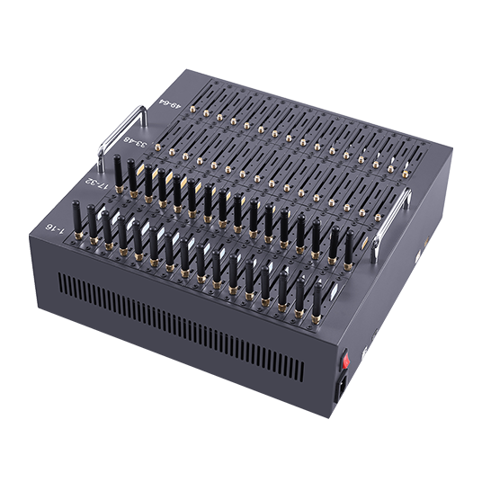
The published range steps from the 8-port TYH modem at $113.00 and the 16-port model at $148.00 to the 32-port model at $270.00 and the 64-port model at $579.00. The step from 32 to 64 ports costs $309.00, which is less than the engineering time that a marginal power and topology design tends to consume.
Three signals indicate the crossover has been reached. Where the host needs to be re-specified to carry the pool reliably, the pool is no longer a desktop device. Where the enclosure requires forced ventilation to remain stable under sustained load, the deployment has become a facilities question. And where the module count makes manual SIM handling impractical, the SIM layer should be planned separately rather than as an attribute of the pool.
Where the deployment needs many numbers rather than many channels, the constraint has moved to the SIM layer, and the calculation changes. In that case the pool may be correctly sized while the estate is not, and the remedy is at the SIM layer rather than at the port count.
How do you diagnose a port that drops under load?
Separate power from topology with one measurement.
The two causes produce similar symptoms and require different remedies.
- Record registered channel count at idle. This is the baseline to compare against.
- Watch the same figure during a batch. A count that falls during transmission points at power or topology; a count that holds points at the network.
- Move the affected module to a different controller. Where the fault follows the controller rather than the module, topology is the cause.
- Test with a reduced batch. Where the fault disappears at lower simultaneous transmission, the supply is under-rated for the peak.
- Swap the module. Where the fault follows the module regardless of port or controller, the module itself is faulty.
Step three is the most informative and the least used. It converts an ambiguous symptom into a definite answer about whether the constraint is electrical or structural, and it takes minutes rather than a spare device.
Where the fault is intermittent across different modules rather than fixed to one, the pattern points at the supply or the hub rather than at any individual component. Intermittency that follows the batch pattern rather than the module is the signature of a shared constraint.
What should the acceptance test cover?
Registered channels at idle, at load, and after warm-up.
The three measurements answer different questions, and only the second and third predict production behaviour.
At idle, confirm the registered count matches the modules installed; a shortfall here is a driver or discovery issue. During a batch, confirm the count does not fall, which is the power and topology test. After a sustained run, confirm the count is unchanged once the enclosure has reached temperature, which is the thermal test. Then confirm the throughput curve flattens at the expected point rather than earlier, which establishes whether the host path is the constraint.
Record the throughput baseline alongside the configuration. A later comparison against a recorded figure distinguishes a genuine change in conditions from a degradation in the deployment, and those two lead to different actions.
Where the deployment is expected to grow past 32 ports, record the host arrangement alongside the pool size. A host that carries 32 modules on a distributed controller arrangement may not carry 64 on the same design, and the growth decision is a host decision as much as a pool decision. Recording the arrangement makes the next step a planned change rather than a discovery.

Module behaviour is documented by Quectel and SimCom, and the messaging standards underneath are published by 3GPP. Where the pool operates in a facility with an environmental specification, the guidance published by ASHRAE and the environmental test standards published by the International Electrotechnical Commission are the normal references, and the ETSI standards catalogue covers the equipment side.
Conclusion
A 32-port pool is where power and USB topology become the engineering problems rather than the radios. Power should be sized for simultaneous transmission and confirmed with the vendor rather than derived from an idle figure, and the host’s USB arrangement determines whether the aggregate throughput is limited by the modules or by the path they share. The diagnostic that separates the two causes is whether the registered channel count falls during a batch.
The crossover to a larger pool or a rack solution is reached when the host has to be re-specified, when the enclosure needs forced ventilation, or when manual SIM handling becomes impractical. The published step from the 32-port model at $270.00 to the 64-port model at $579.00 costs less than the engineering time a marginal host design usually consumes, and it is worth evaluating before rather than after the first difficult batch.
Measure registered channels during a batch, not before it. Send your pool size, host arrangement and throughput requirement to service@telarvo.com, or review the published models on the SMS modem solution pages.
FAQ
Why do modules drop during a batch and recover afterwards?
That pattern points at the power supply. Modules draw their peak current while transmitting, so a supply sized for idle draw experiences a voltage dip when many transmit at once, and modules that see the dip deregister rather than failing outright. Size the supply for simultaneous transmission and confirm registered channel count while a batch is running.
How much power does a 32-port pool need?
Confirm the peak figure with the vendor rather than deriving it from an idle specification, because the ratio between the two differs by module generation. Then size the supply for the case where every module transmits at once, and confirm the host’s per-port current limit as well as its total output if the pool is bus-powered.
Why does throughput stop rising when I add more modules?
Because the path is the constraint rather than the radios. Modules sharing one hub or controller share its bandwidth, so the aggregate flattens once that path is saturated. Measure a throughput curve as modules are added: a curve that flattens before the module count is reached indicates the host arrangement rather than the network.
When should I move to a 64-port or rack solution?
When the host has to be re-specified to carry the pool reliably, when the enclosure needs forced ventilation under sustained load, or when manual SIM handling becomes impractical. The published step from 32 ports at $270.00 to 64 ports at $579.00 costs less than the engineering time a marginal host design usually consumes.