Dual supply protects against one specific thing, and deployments that buy it expecting more are usually disappointed. This article sets out what redundancy covers, what it leaves exposed, and how to test that it works before you need it.
It is written for the people who sign off on a rack rather than the people who switch it on, and it treats a modem pool as a service component rather than as equipment in a cupboard.
What dual power supply for data centre modems protects against
A failure in one power path, and nothing more.
A device with two power inputs and two internal supplies can continue operating when one input loses power or one internal supply fails. That is a real benefit, because a failed power supply is one of the more common hardware faults in equipment that runs continuously, and it is a fault that takes the whole chassis down when there is only one of them. Redundancy converts that from an outage into a maintenance event with a replacement part and a time window.
The benefit only exists if the two inputs are genuinely independent. Two cords plugged into the same power distribution unit meet the letter of dual supply and almost none of its purpose, because a fault in that unit removes both paths at once. The condition to design for is that no single component failure, and no single maintenance action, can interrupt both feeds. That usually means two distribution units on separate circuits, and ideally separate upstream boards.
Resistibility expectations for telecommunications equipment, including what it should tolerate on its power and signal ports, are set out in recommendations such as ITU-T K.20, with the associated test methods in ITU-T K.21 and ITU-T K.44. They are useful mainly as a vocabulary for the questions to ask, because a device that tolerates more on its ports fails less often for reasons nobody will ever diagnose.
What it does not protect against
It does not protect against the failure of anything upstream of the two feeds.
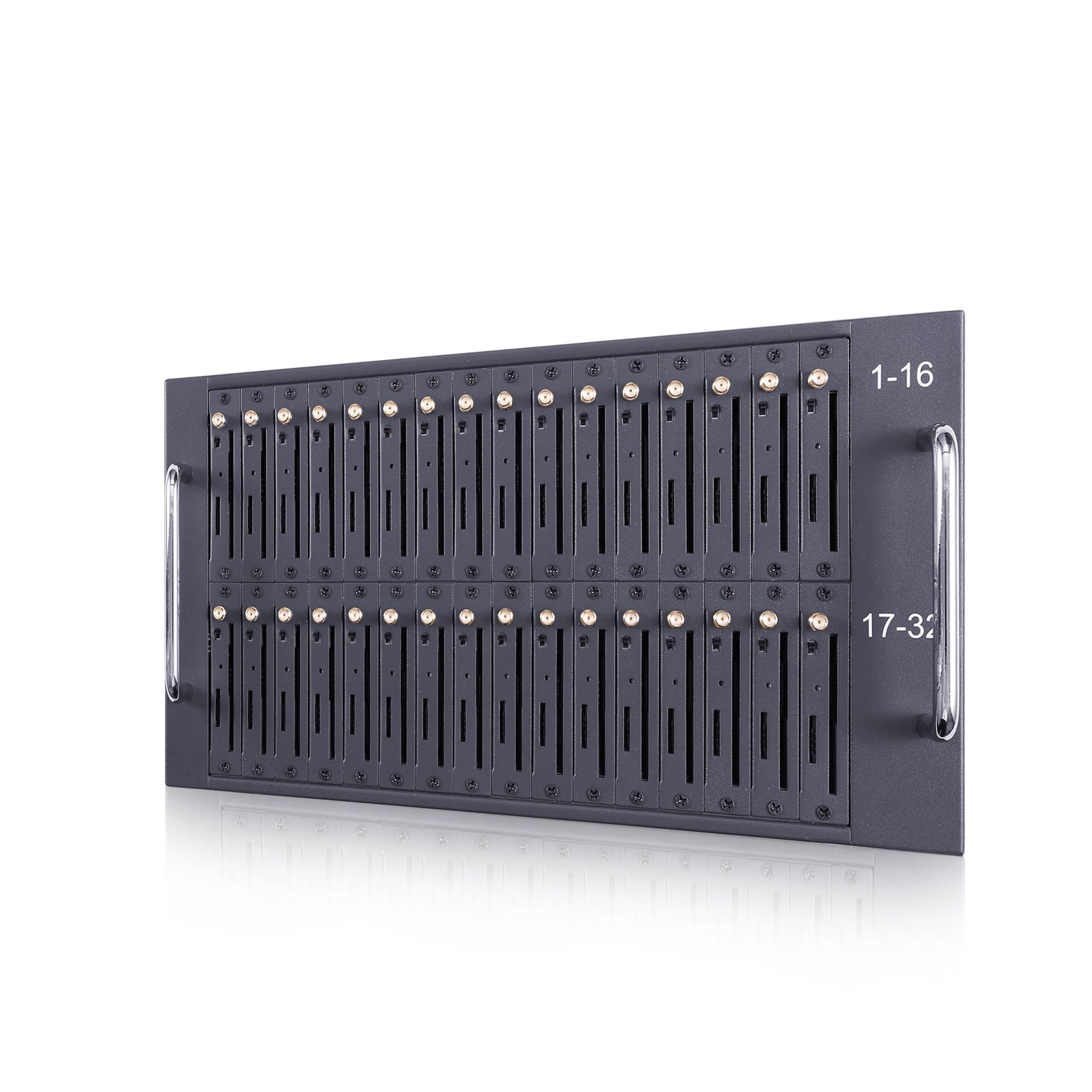
Four exposures sit outside the scope of dual supply. A shared upstream source, where both feeds trace back to the same board or generator, defeats the redundancy entirely. A cooling failure affects both paths equally and, in a dense modem pool, is a more likely cause of an outage than a power fault. A fault in the device itself, such as a failed module or a corrupted configuration, is unaffected by how many cords are connected. And a human error, such as a maintenance action on the wrong distribution unit, is prevented by labelling and procedure rather than by hardware.
The environmental envelope is the other half of the picture. Equipment classes for fixed installations are defined in ETSI EN 300 019-1-3, one of the ETSI standards, and a room that does not meet the class a device expects will produce failures that no amount of power redundancy can prevent. Where the installation is in an unconditioned space, the honest answer is often that the site needs work before the equipment does.
| Failure | Single supply | Dual supply, independent feeds |
|---|---|---|
| One internal supply fails | Outage | Continues on the other supply |
| One circuit trips | Outage | Continues on the other circuit |
| Upstream board fails | Outage | Outage if both feeds share the board |
| Cooling fails | Outage risk | Outage risk, unchanged |
| Device fault | Outage | Outage, unchanged |
The transfer gap and what happens to the queue
Switching power is not the same as continuing to run.
Two designs are sold as redundancy and they behave differently. A dual-redundant design has two supplies operating in parallel, so losing one changes nothing visible: the device keeps running, and the log records a supply loss if the device reports it. A transfer design switches from one input to another, and the switching takes time. During that time the device may hold state, may restart, or may reset its radio modules, and the outcome depends on the hardware rather than on the power arrangement.
What happens to the message queue in that window is the question to ask before purchase, because it determines whether the outage is invisible or expensive. Three outcomes are possible. The queue is held in non-volatile storage and resumes where it stopped, which is the best case. The queue is held in memory and is lost, which means the application must resend and must therefore be able to identify what was lost. Or the modules reset and re-register, which adds a delay during which the pool delivers nothing and then a burst as modules come back.
None of those outcomes is disqualifying, but they lead to different application design. An application that assumes delivery continues through a power event will behave badly with hardware that reboots; an application designed to reconcile an unknown outcome after a restart will manage with either. The specification to ask for is not whether the device has two power inputs but what happens to in-flight work when one of them is removed.
Sizing circuits for peak rather than idle
The figure that matters is the one you cannot measure from a specification sheet.
Published product pages for modem and gateway hardware generally describe ports, formats and interfaces rather than power draw, so the rating has to be confirmed with the supplier for the specific model and configuration. Once it is, the circuit should be sized for the worst case rather than the observed average. In a modem pool the worst case arrives immediately after an outage, when every module re-registers at once and the pool works harder than it does in steady state.
That has two consequences for the rack design. The first is headroom: a circuit loaded to its limit in normal operation has nothing left for the recovery burst, and a protection device that trips during re-registration turns a brief power event into a longer outage than the event itself. The second is the distribution unit rating, which should be chosen for the growth the rack is expected to carry rather than for the equipment installed on the day it is commissioned.
Recording the measured current in steady state and during the first minutes after a simulated restart gives the next engineer both numbers, and it is the evidence that shows whether the circuit has room for another chassis.
Testing the transfer
An untested redundancy feature is an assumption rather than a control.
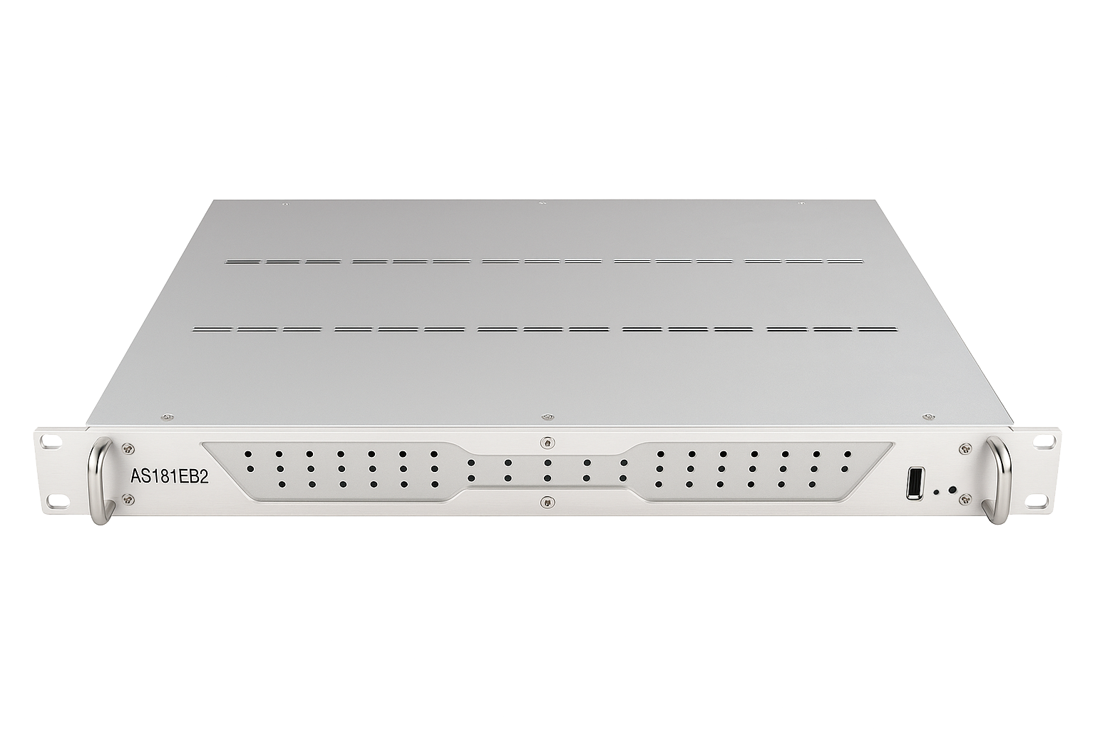
The test is straightforward and should be done before the deployment carries production traffic, then repeated at a defined interval. With the device running and carrying a known load, remove one feed and observe. What matters is not whether the device stays up, which the design may or may not promise, but how long any interruption lasts, whether the modules re-register without intervention, whether in-flight messages are delivered or must be resent, and what the device recorded about the event.
Three things should be written down as a result: the observed interruption, the behaviour of the queue, and the recovery time for the pool to return to normal throughput. Those three numbers are the acceptance criteria for the redundancy feature, and without them the phrase dual power supply describes a connector rather than a capability.
Both numbers belong in an operational record rather than in an engineer’s notebook, and the practice of protecting and retaining that kind of evidence is described in NIST SP 800-92, which is a short and practical reference.
The repeat interval matters for the same reason it does with any untested control. A transfer mechanism that worked at commissioning can stop working after a firmware change or a distribution rework, and neither event announces itself. An annual test performed in a planned window is usually enough, provided the result is recorded alongside the original figures.
Cost against benefit at different scales
Redundancy is cheap insurance at scale and expensive overhead below it.
At the scale of a single chassis serving a small office, the case is weak. A well-protected single supply with an uninterruptible power supply covers the common case, which is a brief mains interruption, and the cost of a second circuit and a second distribution unit is difficult to justify against the downtime it would prevent. The exception is a deployment whose failure carries a regulatory or contractual consequence, where the justification is written into the obligation rather than into the arithmetic.
At the scale of a data centre rack serving many subscriptions, the case is strong for a different reason. A rack holding several chassis concentrates a great deal of capacity into one position, so the consequences of a single supply fault grow with the density while the cost of redundancy stays roughly constant per chassis. The same logic applies to the antenna and network paths: at higher density, single points of failure become more valuable to remove.
The intermediate case, two or three chassis in an equipment room, is decided by what the business does during an outage. Where a failure means messages queue and are delivered late, the modest arrangement is adequate. Where it means verification codes do not arrive for the duration, the second circuit is cheaper than the incident review that follows.
A power design checklist
The checklist covers the decisions that determine what a modem deployment can survive and how quickly a fault is found. Two items, the independence of the feeds and the behaviour of the queue during a transfer, decide the outcome; the rest determine how the design is verified and maintained.
- Two feeds traced back to separate boards, not two cords from one unit.
- Published power rating confirmed with the supplier for the exact model and configuration.
- Circuit sized for the re-registration burst rather than the steady-state load.
- Distribution unit rated for the growth the rack is expected to carry.
- Documented behaviour of the message queue when one feed is removed.
- Recorded transfer test result: interruption, queue behaviour, recovery time.
- Environmental class of the room matched to the class the equipment expects.
- Labelling and procedure that prevent maintenance on the wrong feed.
Ask what happens to the queue, not how many cords fit. Send your rack layout, circuit arrangement and recovery requirements to service@telarvo.com, or review the published configurations on the SMS modem range and the SMS modem solution page. Telarvo publishes the SK-SMS gateway range, the TYH modem pools and the TGW SMS machine on its product pages, and the configurations referenced above come from those listings.
FAQ
Do I need dual power supply for a modem rack?
It depends on what a power interruption costs you. For a single chassis in a small office with an uninterruptible supply, the second feed is usually hard to justify. Where a rack concentrates many subscriptions, or where a failure carries a contractual or regulatory consequence, redundancy is worth more than it costs, because the consequence of one fault grows with density while the cost of redundancy does not.
Can two cords from the same PDU be called dual supply?
Physically yes, but the protective value is almost nil. A fault in that distribution unit removes both paths simultaneously, which is the most common way redundancy is defeated in practice. For dual supply to mean anything, the two feeds should trace back to separate circuits and ideally separate boards, so that no single failure or maintenance action can interrupt both at once.
What happens to queued messages when one power feed fails?
That depends on the design, and it is worth confirming in writing before purchase. Some hardware holds the queue in non-volatile storage and resumes where it stopped; some holds it in memory and loses what was in flight; some resets the radio modules, which introduces a gap followed by a reconnect burst. The first outcome is the easiest to live with, but any of them can be handled if the application can reconcile an unknown outcome.
How often should a power transfer be tested?
Before the deployment carries production traffic, and then at a planned interval such as annually. The test should record three values: the length of any interruption, what happened to in-flight messages, and how long the pool took to return to normal throughput. A redundancy feature that has never been exercised is an assumption rather than a control, because transfer mechanisms can stop working after a firmware change or a distribution rework.
{
“@context”: “https://schema.org”,
“@type”: “FAQPage”,
“mainEntity”: [
{
“@type”: “Question”,
“name”: “Do I need dual power supply for a modem rack?”,
“acceptedAnswer”: {
“@type”: “Answer”,
“text”: “It depends on what a power interruption costs you. For a single chassis in a small office with an uninterruptible supply, the second feed is usually hard to justify. Where a rack concentrates many subscriptions, or where a failure carries a contractual or regulatory consequence, redundancy is worth more than it costs, because the consequence of one fault grows with density while the cost of redundancy does not.”
}
},
{
“@type”: “Question”,
“name”: “Can two cords from the same PDU be called dual supply?”,
“acceptedAnswer”: {
“@type”: “Answer”,
“text”: “Physically yes, but the protective value is almost nil. A fault in that distribution unit removes both paths simultaneously, which is the most common way redundancy is defeated in practice. For dual supply to mean anything, the two feeds should trace back to separate circuits and ideally separate boards, so that no single failure or maintenance action can interrupt both at once.”
}
},
{
“@type”: “Question”,
“name”: “What happens to queued messages when one power feed fails?”,
“acceptedAnswer”: {
“@type”: “Answer”,
“text”: “That depends on the design, and it is worth confirming in writing before purchase. Some hardware holds the queue in non-volatile storage and resumes where it stopped; some holds it in memory and loses what was in flight; some resets the radio modules, which introduces a gap followed by a reconnect burst. The first outcome is the easiest to live with, but any of them can be handled if the application can reconcile an unknown outcome.”
}
},
{
“@type”: “Question”,
“name”: “How often should a power transfer be tested?”,
“acceptedAnswer”: {
“@type”: “Answer”,
“text”: “Before the deployment carries production traffic, and then at a planned interval such as annually. The test should record three values: the length of any interruption, what happened to in-flight messages, and how long the pool took to return to normal throughput. A redundancy feature that has never been exercised is an assumption rather than a control, because transfer mechanisms can stop working after a firmware change or a distribution rework.”
}
}
]
}