Signal drops on a 32-port SMS modem rack are reported as one fault and produced by three: radio conditions, power behaviour and heat. They look identical in the interface because the interface only shows the result.
This guide separates them with measurements taken at the installed position, then covers the antenna routing and interference issues that appear specifically when many radios share a rack, the power behaviour that only shows during simultaneous transmission, and a diagnostic order that avoids swapping parts until something changes.
Which three causes produce identical signal drops on a 32-port SMS modem rack?
Radio conditions, voltage sag and thermal rise.
All three remove a module from the network and allow it to return, so the interface reports the same state change whether the cause is coverage, supply or temperature.
Separating them is a matter of timing rather than of instrumentation. Radio conditions vary with position and with the environment, so they differ between slots in the same rack. Voltage sag appears at the instant load rises and affects the modules whose supply path is weakest, which usually means the same set of slots every time. Thermal rise appears after sustained transmission and affects the modules with the least airflow, which in a vertical rack means the upper rows.
Those three signatures are the whole diagnostic method, and they cost nothing to collect. Record, for each drop, the slot, the time, the elapsed transmission time and the rack row. A pattern will be visible within a day of normal operation, and the pattern names the cause before any tool is connected.
| Cause | Signature in the record | Where it clusters |
|---|---|---|
| Radio conditions | Random in time, stable per position | Specific slots regardless of load |
| Voltage sag | Instantaneous, on load rise | The same slots on every large batch |
| Thermal rise | Delayed, after minutes of transmission | Upper rows and poorly ventilated positions |
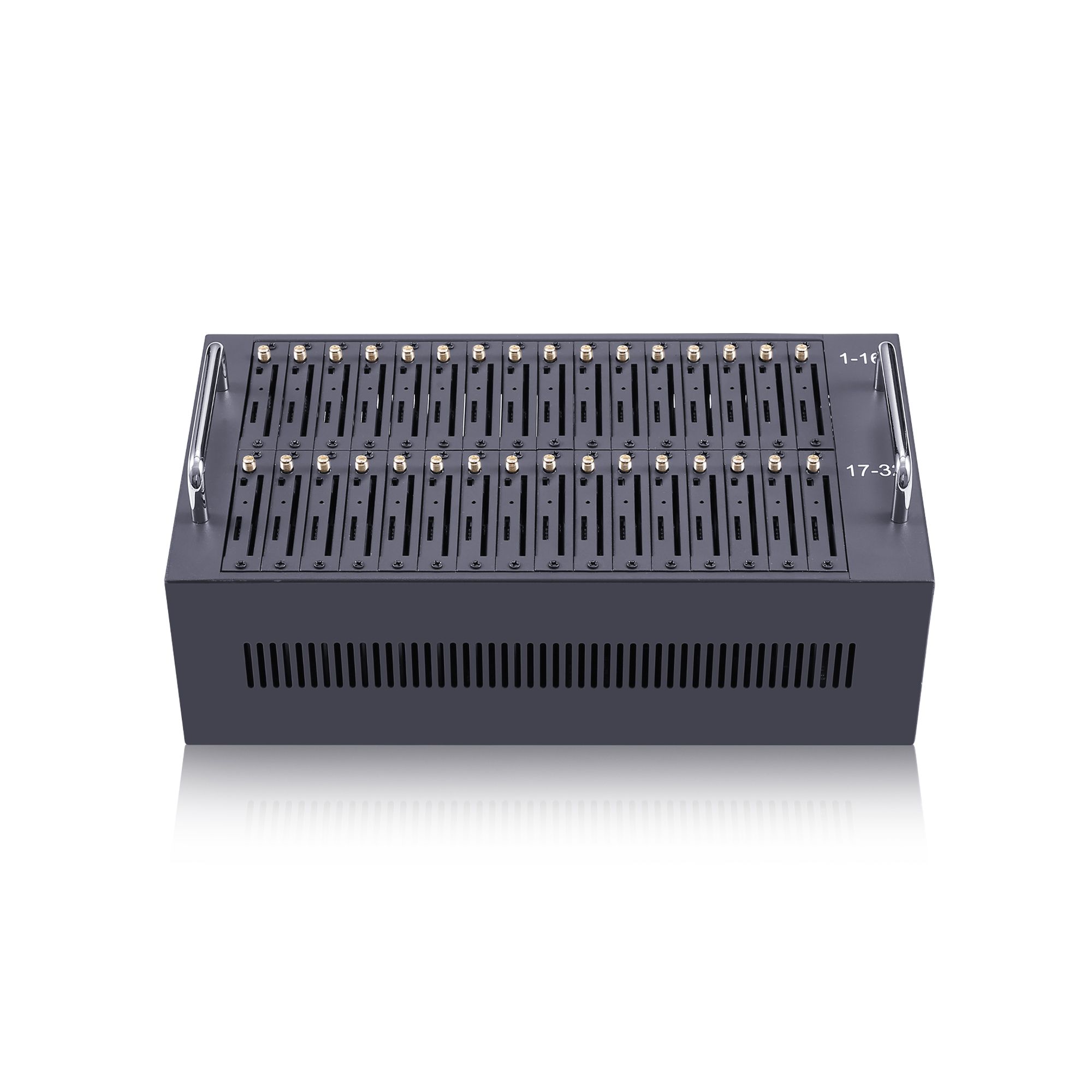
Verifying signal at the installed position, not the bench
Bench measurements describe the bench.
A module tested on a desk sees a different radio environment from the same module inside a metal enclosure between two other modules, and the difference is large enough to change the result.
The installed position introduces three variables that a bench test removes: the enclosure, the neighbouring modules and the cable route to the antenna. Metal panels reflect and absorb, neighbouring transmitters add noise, and a longer cable run costs signal that a short test lead did not. That is why a rack can pass commissioning and still deliver poorly, and why the first measurement in any investigation should be taken where the equipment actually operates.
Measure per slot, at the installed position, with the rack populated and traffic flowing. Record the reading and the position together, because the figure alone cannot be compared with a later measurement taken after a module has moved. Where the equipment is specified against a harmonised terminal standard such as ETSI EN 301 511, the conditions under which it was tested are the conditions the installation should approximate.
Take the measurement twice, once with the enclosure open and once closed, and keep both figures. The difference between them is the enclosure penalty for that position, and it is the number that tells you whether moving the antenna or moving the module is the more useful change. Positions with a large penalty are the ones to address first, because the cost of fixing them is bounded and the benefit applies to every message the slot carries.
Antenna routing out of an enclosed rack
An antenna inside a closed cabinet is a design fault, not a marginal one. Metallic enclosures attenuate the signal path in both directions, and the attenuation is frequency-dependent and hard to predict, so the result is a link that works until the door is closed and then degrades unpredictably. Routing antennas outside the enclosure is usually the single change that produces the largest improvement, and it costs cabling rather than hardware.
Two details decide whether the change delivers. The first is cable loss: longer routes and thinner cable reduce the signal delivered to the antenna, and the loss grows with frequency. Keep runs as short as the layout allows and record the cable type, because a later rearrangement that lengthens a run silently changes the installation. The second is separation between antennas. Two antennas close together couple with each other, which reduces the benefit of having two and can make performance worse than a single well-placed antenna.
Take the reading before and after every routing change, at the same slots and under the same load. Without a before-and-after pair, the change cannot be shown to have helped, and the next person to touch the rack will undo it.
Interference between radios at density
Dense transmitters raise the noise floor for each other. When dozens of radios transmit within the same small volume, each one contributes energy that the others receive, and the effect is not a single dramatic failure but a slow reduction in the quality of every link. The practical symptom is a rack whose slots individually perform adequately and whose aggregate delivery ratio is worse than any single slot suggests.
Transmission timing is the lever. Where the platform offers control over when modules transmit, spreading bursts in time reduces the overlap between transmitters and lowers the aggregate noise. Where it does not, physical arrangement is the remaining control: separating modules, orienting their antennas to reduce coupling and avoiding positions directly in front of another transmitter.
Radio transmission and reception characteristics, including the conditions under which terminal equipment is specified, are set out in 3GPP TS 45.005. The specification is not a rack design guide, but it is a useful reference for what the equipment is expected to tolerate and for the vocabulary of the measurements you will take.
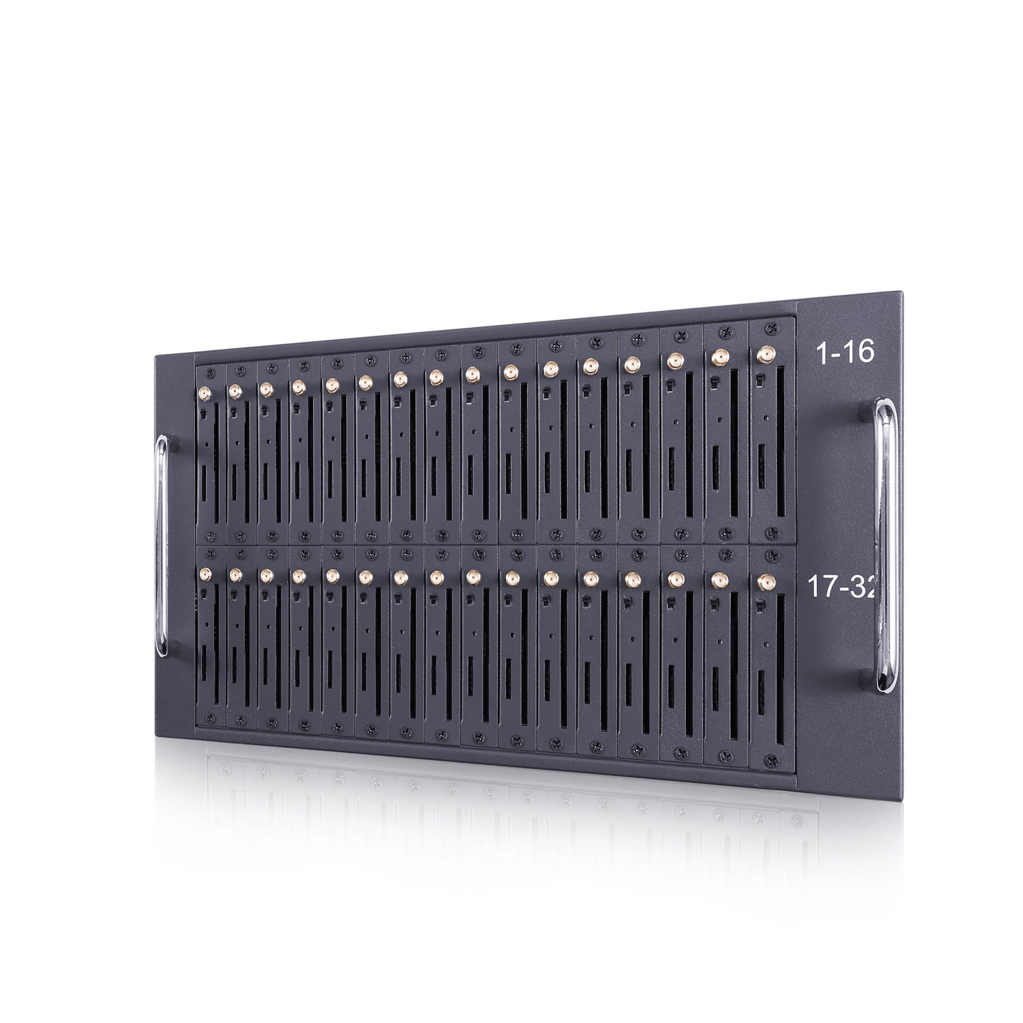
Power dips during simultaneous transmission
The supply is tested once, under load. A rack that draws a modest current at idle can draw several times that when every module transmits at once, and a supply or distribution path sized for the idle figure will sag at the peak. The result is a module that resets, re-registers and appears healthy by the time anyone looks, which is why the failure is recorded as a signal drop rather than as a power event.
Measure the rail at the point of load, not at the supply terminals, and measure it twice: at idle and during a full batch. The difference between the two readings is the number that matters. Resistibility recommendations for telecom equipment against surges and overvoltages, including ITU-T K.20 and ITU-T K.21, describe the classes of environment equipment may be exposed to, and ITU-T K.44 covers the test regime behind them.
Where the dip is confirmed, the remedy is distribution rather than more capacity: shorter and thicker runs, fewer modules behind a single branch, and a supply whose output is specified at the peak rather than the average. Confirming the cause is worth the effort, because a power problem that is treated as a radio problem produces a rack full of replaced modules and no improvement.
A diagnostic order that avoids substitution
Measure before you swap. Substitution is the fastest way to spend a day and learn nothing, because it changes several variables at once and destroys the record that would have identified the cause.
- Record every drop with slot, time, elapsed transmission time and rack row for one full day.
- Read the pattern against the three signatures and state a hypothesis before touching anything.
- Measure the supply rail at the point of load at idle and at peak.
- Measure signal per slot at the installed position with the rack populated.
- Test the hypothesis with one change, then repeat steps one and two.
- Keep the before-and-after pair for every change, including the ones that did not help.
Module attach and re-registration are network procedures described in 3GPP TS 24.301, which is worth skimming once so that the states in the record can be read correctly. The point of the order above is not the individual measurements but the requirement to form a hypothesis before acting on it.
Recording an installation baseline
A baseline turns the next incident into a comparison. For each slot, record the installed position, the antenna route and cable type, the signal reading under load, the supply rail reading at idle and at peak, and the airflow arrangement. Add the rack population and the date.
Keep the record with the configuration rather than in a project file, because the events that invalidate a baseline are operational: a module is replaced, a cable is rerouted, a card is added to the rack. Each of those changes the signal environment, and none of them is recorded unless the baseline lives where the work happens.
Two additions make the record usable by someone who was not present when it was taken. The first is a photograph of the rack with the positions labelled, because a description of antenna routing is far harder to interpret than an image of it. The second is the load profile under which the readings were taken, since a signal figure recorded at idle and one recorded during a batch are not the same measurement and should never be compared as if they were.
Record one day of drops before you replace a module. Send your drop pattern, supply readings and rack layout to service@telarvo.com, or review the published configurations on the SMS modem range and the SK-SMS Gateway range. Telarvo publishes the SK-SMS gateway range, the TYH modem pools and the TGW SMS machine on its product pages, and the configurations referenced above come from those listings.
FAQ
Why do the same slots drop every time?
Repetition narrows the cause to something positional. A repeating set of slots points to the supply path or the airflow reaching those positions rather than to the radio, because radio conditions vary more than that. Measure the rail at the point of load and check whether the repeating slots share a branch or a rack row. Shared position, shared cause is the working rule.
Can antennas be left inside a closed rack?
They can be, but the enclosure attenuates the signal in both directions and the result is difficult to predict or to compare between installations. Routing antennas outside the enclosure is usually the highest-return change available, provided the cable run is kept short and the loss of the cable type is recorded. Record the measured signal at the module before and after, so the benefit is a number rather than an impression.
Does adding modules always reduce signal quality?
It raises the noise floor when several modules transmit at once, so aggregate quality can fall even though each individual link is adequate. Spreading transmissions in time and separating antennas reduces the overlap. Measure the aggregate delivery ratio after each addition rather than assuming a linear scale-up. Where the ratio falls as ports are added, the constraint is the radio environment rather than the hardware.
How do we tell a power drop from a radio drop?
Timing is the discriminator. A power problem appears at the instant load rises and affects the same slots each time, while a radio problem is stable per position and independent of load. One day of records with elapsed transmission time per event separates the two without any additional instrumentation. Add the supply reading at the moment of the event where the device can report it, because that closes the question.
{
“@context”: “https://schema.org”,
“@type”: “FAQPage”,
“mainEntity”: [
{
“@type”: “Question”,
“name”: “Why do the same slots drop every time?”,
“acceptedAnswer”: {
“@type”: “Answer”,
“text”: “Repetition narrows the cause to something positional. A repeating set of slots points to the supply path or the airflow reaching those positions rather than to the radio, because radio conditions vary more than that. Measure the rail at the point of load and check whether the repeating slots share a branch or a rack row. Shared position, shared cause is the working rule.”
}
},
{
“@type”: “Question”,
“name”: “Can antennas be left inside a closed rack?”,
“acceptedAnswer”: {
“@type”: “Answer”,
“text”: “They can be, but the enclosure attenuates the signal in both directions and the result is difficult to predict or to compare between installations. Routing antennas outside the enclosure is usually the highest-return change available, provided the cable run is kept short and the loss of the cable type is recorded. Record the measured signal at the module before and after, so the benefit is a number rather than an impression.”
}
},
{
“@type”: “Question”,
“name”: “Does adding modules always reduce signal quality?”,
“acceptedAnswer”: {
“@type”: “Answer”,
“text”: “It raises the noise floor when several modules transmit at once, so aggregate quality can fall even though each individual link is adequate. Spreading transmissions in time and separating antennas reduces the overlap. Measure the aggregate delivery ratio after each addition rather than assuming a linear scale-up. Where the ratio falls as ports are added, the constraint is the radio environment rather than the hardware.”
}
},
{
“@type”: “Question”,
“name”: “How do we tell a power drop from a radio drop?”,
“acceptedAnswer”: {
“@type”: “Answer”,
“text”: “Timing is the discriminator. A power problem appears at the instant load rises and affects the same slots each time, while a radio problem is stable per position and independent of load. One day of records with elapsed transmission time per event separates the two without any additional instrumentation. Add the supply reading at the moment of the event where the device can report it, because that closes the question.”
}
}
]
}