Device registration checks on a high-density modem rack are usually treated as a one-off commissioning step, and that is why deregistration under load takes teams by surprise. The state that matters is the one the rack holds at peak, not the one it held on the bench.
This checklist separates the two conditions that dashboards merge, sets out what to read per slot during a batch, and covers the two physical causes that produce intermittent deregistration at density: power stability and thermal behaviour. It closes with an acceptance test you can repeat after any change.
What do modem rack device registration checks actually confirm?
It confirms the network accepted this subscriber.
Registration is the result of a signalling exchange in which the module identifies itself to the network and the network accepts it, so a successful registration is a statement about both sides rather than about the module alone.
The attach procedure that precedes a usable data or messaging state is defined in the non-access-stratum protocol specified in 3GPP TS 24.301. What matters operationally is that the exchange can succeed and then be withdrawn: the network can detach a subscriber, the module can lose the radio, and the subscription can be refused for reasons that have nothing to do with the hardware.
A registration check that only asks “is it registered?” therefore answers the least useful version of the question. The useful version asks when it registered, how long it has held that state, and whether it has re-registered repeatedly. A slot that has registered eleven times in an hour is technically registered at the moment you look and is also the slot you should investigate.
What is the difference between attached and registered?
Attachment is a radio state; registration is a network one.
A module can be attached and not registered, which is exactly the state that produces a rack that looks connected while no message leaves it.
Attachment is a radio-level condition: the module has found a cell and established the link. Registration is a network-level condition: the subscriber is known to the core and permitted to use services. Between the two sit the identity checks that the network performs, and those are where a misprovisioned subscription is caught.
The practical consequence is that a signal-strength indicator is not a health check. Signal strength describes the radio leg, and a rack can report excellent signal on every slot while half the subscribers are refused service. Treating bars as a proxy for registration is the single most common reason a modem rack looks healthy during a failure.
| State | What it proves | What it does not prove |
|---|---|---|
| Attached | The module found a cell and holds a radio link | That the subscriber may send or receive anything |
| Registered | The network accepted the subscriber | That the subscription is in credit or permitted for bulk use |
| Signal strength | The quality of the radio leg | Anything about the network-side decision |
| Session active | Traffic can flow now | That it will still flow in ten minutes |
How do you check per-slot state during a batch?
Read the counters while traffic is flowing, not before.
Sample each slot at three points during a batch — start, peak and tail — and record registration state alongside the send attempt count, so deregistration can be linked to load.
Commissioning tests are usually run against an idle rack, which is the one condition under which a power or thermal margin never gets tested. Sampling during a batch is what exposes a slot whose registration survives at rest and fails when twenty modules transmit at once. The command interface available for polling is specified in ETSI TS 127 005, and the practical constraint is polling frequency: reading every slot every second can itself contribute to the load you are trying to measure.
Record four values per slot per sample: registration state, cumulative send attempts, cumulative failures since the last sample, and the timestamp. That set is small enough to collect continuously and rich enough to distinguish a slot that never registered from one that deregisters under load, which is the distinction the whole exercise exists to make.
Power stability as a cause of deregistration
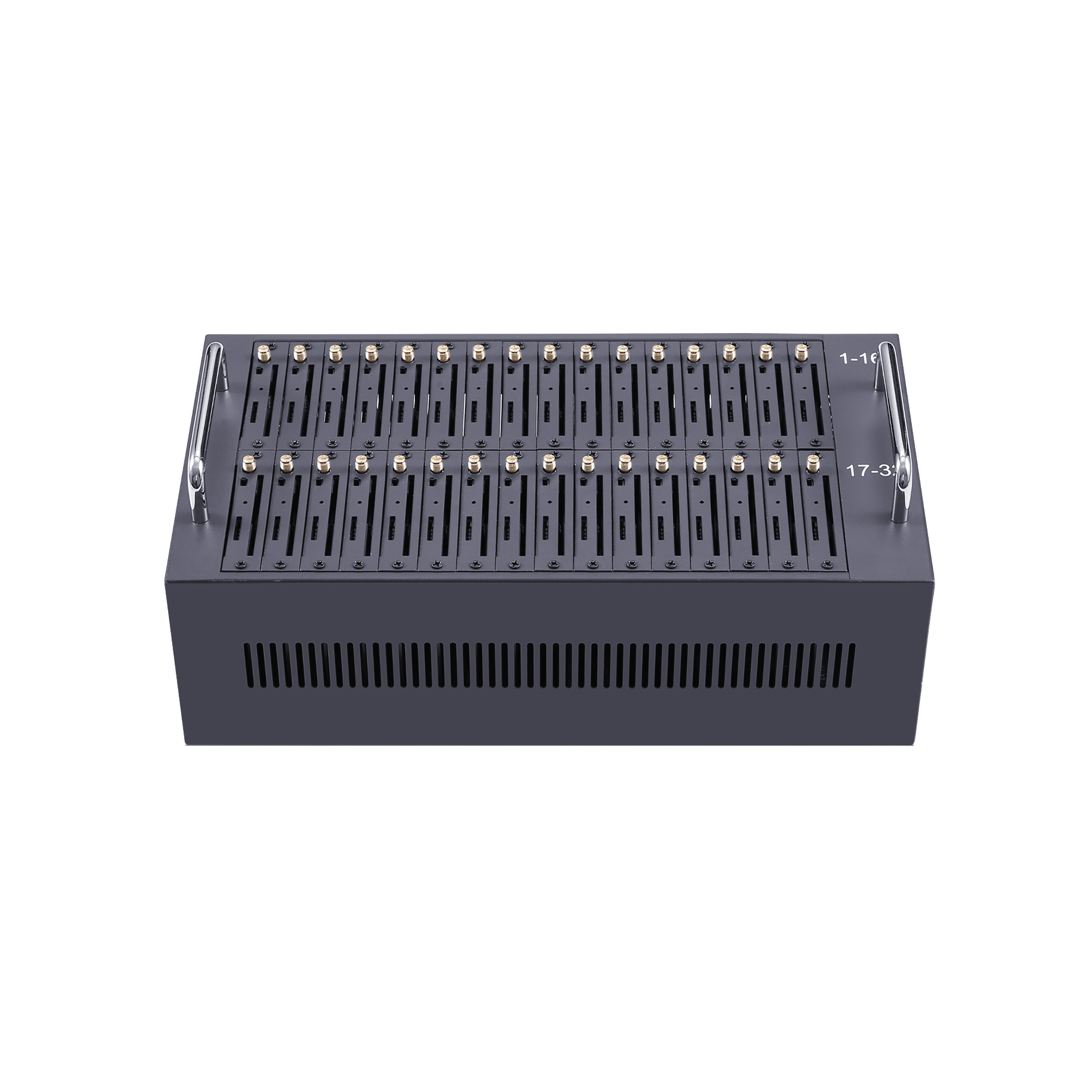
Simultaneous transmission is the moment a marginal supply fails. When twenty or thirty radio modules begin transmitting within the same second, current draw rises sharply, and a supply that was adequate at idle can sag enough to reset a module — after which the slot re-registers and the log shows a healthy state a minute later. This is why intermittent deregistration so often correlates with message bursts rather than with time of day.
The counter-intuitive part is that the failure is not random. It clusters on the slots that transmit first and on the slots furthest from the supply, and the clustering is the evidence. A rack where the same four slots deregister on every large batch has a distribution problem, not a radio problem. Resistibility requirements for telecom equipment against overvoltage and current surges are the subject of the ITU-T K.21 recommendation, and they are a useful reference when specifying what the installation should tolerate.
Check the supply rails while a batch runs, at the rack end rather than at the supply terminals, and compare the reading at idle with the reading at peak. If the difference is larger than the modules tolerate, the fix is a supply and distribution change, not a configuration change.
Thermal behaviour at rack density
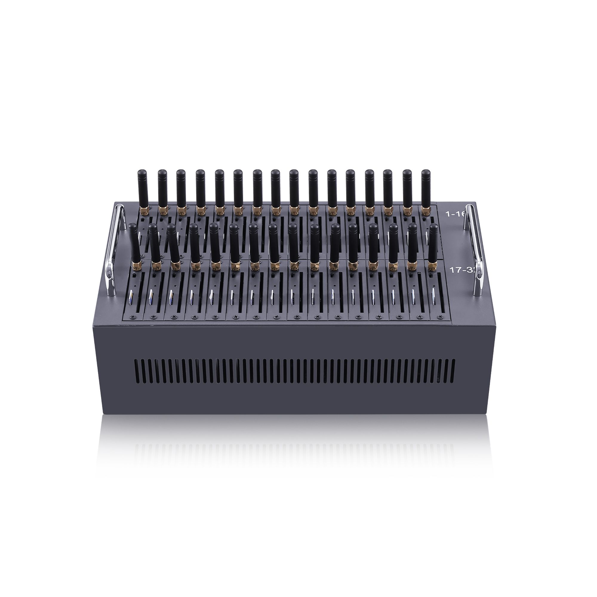
Density converts an adequate thermal design into a marginal one. Modules in a fully populated rack sit in the exhaust of the modules below them, and the internal temperature of a module that has been transmitting for twenty minutes is materially higher than that of one that has been idle. Thermal behaviour is where the difference between a bench test and a rack installation becomes visible, and the radio transmission and reception characteristics of the terminal equipment are standardised in 3GPP TS 45.005, including the conditions under which the equipment is specified.
Two measurements tell you whether thermals are implicated. The first is the correlation between deregistration events and elapsed transmission time: thermal problems appear after minutes of load, while power problems appear at the instant load rises. The second is the vertical distribution of failures within the rack, because heat accumulates upward.
If failures cluster on the upper rows and appear late in a batch, the remedy is airflow rather than configuration: more space between units, intake air that is not already warm, and a rack position that is not in a dead zone of the room. Where the equipment is specified to a harmonised terminal standard such as ETSI EN 301 511, the environmental envelope the manufacturer designed for is the one the installation has to respect.
What are device identity checks for, and what are their limits?
They are for inventory, warranty and fault attribution.
Reading the identity a module reports is a legitimate operations task that helps you match a physical unit to a record; changing that identity is a different matter entirely and not a configuration option.
A rack with dozens of modules needs a reliable way to answer “which unit is this?” when a slot misbehaves, and reading the reported identity is how that mapping is maintained. It supports spare-part planning, warranty claims and root-cause analysis across a fleet. Its limit is that it identifies hardware, not permission: a module whose identity record is correct can still be refused service because the subscription behind it is not entitled to the traffic being sent.
Treat identity data as inventory data with a retention policy, because it is linkable to a subscription. Where the rack is shared across customers or markets, keep the mapping in the same system that holds the slot history so the two records cannot drift apart. Logging practice for records of this kind is covered in NIST SP 800-92, which is a reasonable reference even where no formal requirement applies.
A registration acceptance checklist
Run the acceptance test against a loaded rack and keep the result as the baseline for every later comparison. Ten checks cover the states and physical causes that produce the majority of intermittent faults.
The sequence is deliberate: the first three checks establish what the rack does under load, the next three test the two physical hypotheses, and the last four protect the record. Run the whole list once at commissioning and again after any change to the rack population, the supply arrangement or the polling configuration, because each of those changes invalidates a comparison made against the previous baseline.
- Confirm every slot reaches registered state from a cold start, and record the time it takes.
- Sample registration state at start, peak and tail of a full batch, per slot.
- Record cumulative send attempts and failures between samples, not just totals.
- Measure the supply rail at the rack end at idle and at peak.
- Record module temperature or, where unavailable, elapsed transmission time per slot.
- Chart deregistration events by rack row to test the thermal hypothesis.
- Confirm the failure set repeats on consecutive batches before concluding a cause.
- Verify the identity-to-slot mapping after any module swap.
- Keep the polling interval fixed across tests so results remain comparable.
- Store the baseline with the configuration that produced it.
Bring the peak-load sample, not the commissioning sample. Send your rack size, batch profile and supply measurements to service@telarvo.com, or review the published configurations on the SMS modem range and the SIM pool range. Telarvo publishes the SIMBANK and SIMPOOL ranges on its product pages, and the configurations referenced above come from those listings.
FAQ
Why do modems deregister only during large batches?
Because peak load is when the margins are tested. Simultaneous transmission raises current draw and temperature at the same time, so a slot with an adequate margin at idle can reset at peak and re-register before anyone looks. Record the failure set across consecutive batches; a repeating set points to supply or airflow rather than to the radio. A set that moves between batches points at radio conditions instead.
Is signal strength a reliable health indicator for a modem rack?
No. Signal describes the radio leg only. A slot can report strong signal while the subscriber is refused service, and it can report weak signal while delivering reliably. Use signal as one input alongside registration state, send attempts and failures, and treat the combination as the health measure. Recording all four per slot at commissioning gives the baseline that later readings are compared against.
How often should slots be polled during a batch?
Often enough to see a transition and rarely enough not to create one. Three samples per batch, taken at start, peak and tail, are usually sufficient, and a fixed interval keeps results comparable between tests. Polling every slot every second adds management traffic that can itself perturb the measurement. Where a dashboard needs fresher data, export it from the device log rather than shortening the polling interval.
What should an acceptance record contain?
Per-slot registration times from cold start, the three sample points with cumulative attempts and failures, supply readings at idle and at peak, the rack row for each failure, and the polling interval used. Store it with the configuration so a later test compares like with like rather than against memory. Add the firmware version and the ambient temperature, because both change the figures and neither is recoverable afterwards.